

# slurry pump parts diagram(渣浆泵配件结构图完整解析)
## 1. Full Exploded Diagram Overview A standard horizontal centrifugal slurry pump is split into two core modules: **wet end parts** (wear-resistant components contacting slurry) and **drive end parts** (transmission & bearing assembly). All labeled parts match international pump drawing standards for procurement, maintenance and assembly drawing marking. ## 2. Wet End Wearing Parts (Key Spare Parts) These are consumable parts needing regular replacement, the core of slurry pump diagrams: 1. **Impeller** The rotating core component. High-speed rotation generates centrifugal force to push slurry. Closed impellers for fine low-abrasion slurry; open/semi-open impellers for large solid particles. Materials: high-chromium alloy, natural rubber, polyurethane. 2. **Front Liner / Front Guard Plate** Covers the pump inlet, protects pump cover shell from particle abrasion, guides slurry evenly into impeller flow channels. 3. **Back Liner / Rear Guard Plate** Mounted behind the impeller, isolates slurry from shaft seal cavity, cooperates with expeller to reduce slurry leakage to bearing housing. 4. **Volute Casing Liner** Inner wearable lining of pump volute shell, spiral shape matching pump casing. Replaceable instead of whole pump body to cut maintenance cost. 5. **Expeller (Auxiliary Impeller)** Installed on rear of main impeller, creates reverse centrifugal pressure to block slurry from entering shaft seal, reduces seal wear. 6. **Shaft Sleeve** Covers the pump shaft, prevents slurry corrosion and abrasion on main shaft; only replace sleeve when worn to protect expensive pump shaft. ## 3. Pump Housing & Shell Components 1. **Split Volute Casing (Outer Pump Body)** Double-shell structure, vertical split design for easy disassembly. Discharge outlet can be adjusted at 45° intervals in 8 directions to fit pipeline layout. 2. **Pump Cover / Frame Plate Cover** Front sealing cover of pump casing, fixes front liner, connects suction flange. 3. **Frame Plate** Intermediate support connecting wet end and bearing assembly, positions rear liner and seal parts. ## 4. Shaft Seal Assembly (Leakage Prevention) 1. **Expeller Seal Ring** Matches auxiliary impeller to form pressure isolation cavity. 2. **Gland Packing / Mechanical Seal** Two mainstream sealing solutions: packing seal for low-cost general working conditions; mechanical seal for high-concentration, high-pressure slurry with zero leakage requirement. 3. **Packing Gland** Compresses packing filler to adjust sealing tightness.
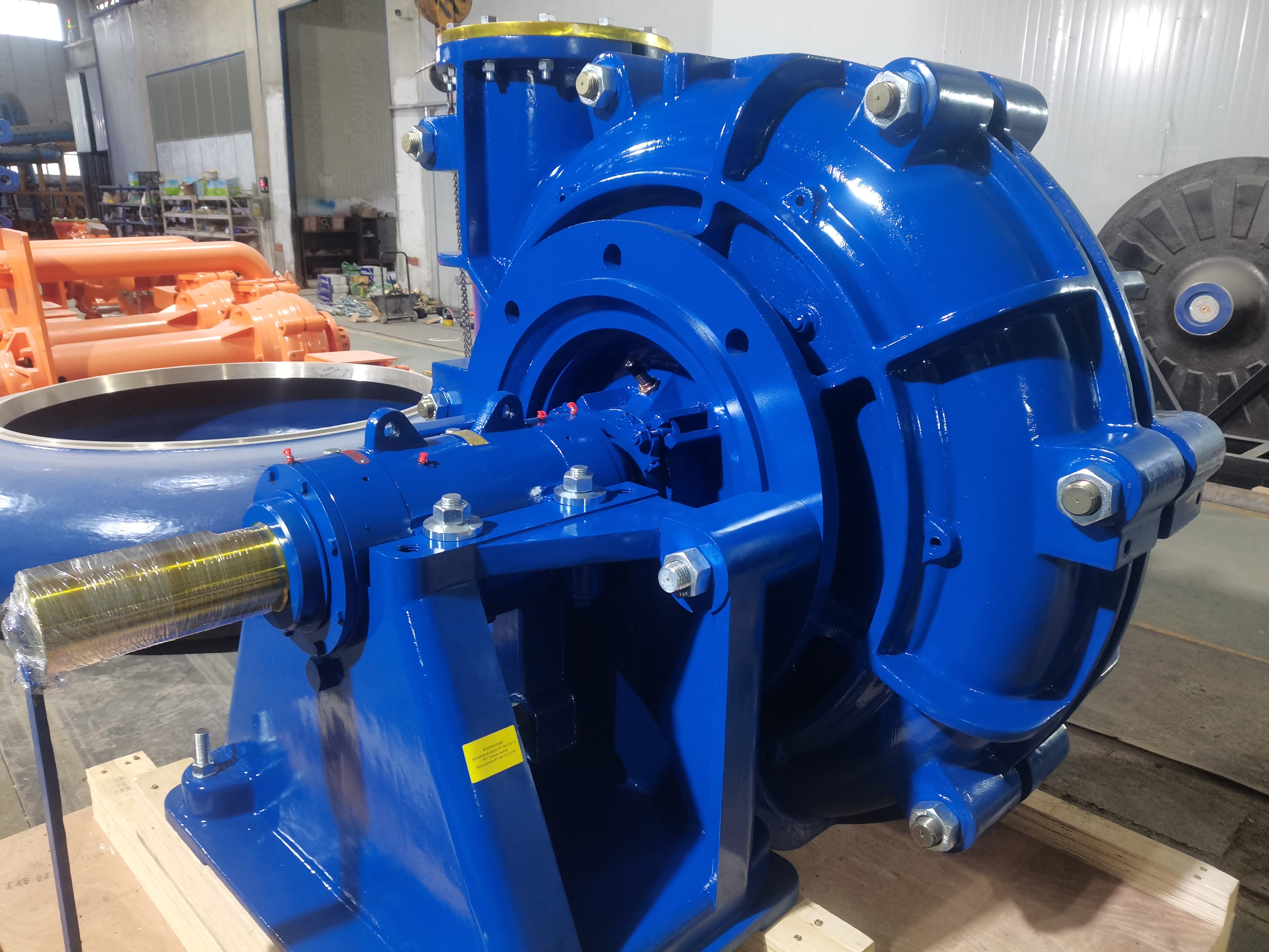 ## 5. Drive End Transmission Parts 1. **Pump Shaft** Transmits torque from motor to impeller, high-strength carbon steel or stainless steel. 2. **Bearing Assembly (Bearing Housing + Roller Bearings)** Supports rotating shaft, bears radial & axial impact loads from slurry. Oversized bearings adopted for heavy abrasion working conditions to extend service life. 3. **Bearing Housing Frame** Carries bearing set, mounted on base stand. 4. **Coupling / Belt Pulley** Connects pump shaft and motor output shaft; belt drive allows adjustable rotation speed, rigid coupling for fixed-speed heavy-duty operation. 5. **Base Stand** Integrated cast base fixing pump and motor, eliminates vibration during operation. ## 6. Standard Diagram Labeling Rule for Drawing 1. Number each part sequentially from slurry inlet to drive end; 2. Mark material grade separately for wet wear parts (Cr27, rubber, PU); 3. Distinguish split solid casing on drawing for model selection reference; 4. Highlight interchangeable spare parts for quick order matching. ## 7. Application Scenarios of Slurry Pump Diagram - Engineering drawing production & OEM part customization - On-site disassembly, overhaul and wear parts replacement - Spare parts inventory classification and sales catalog making - Equipment failure troubleshooting and structural training